Verdict
Key Specifications
- Review Price: £205.72
Gigabyte lists an impressive range of six models of LGA1366 Core i7 motherboards that use the Intel X58 chipset. Most of these models are priced in a narrow range from £189 to £235 with the EX58 Extreme off in the distance at £289. This puts the GA-EX58-UD4P square in the middle of the regular models in terms of price, yet the list of features looks very impressive.
The feature that shapes the layout of the UD4P is the three graphics slots that support both CrossFire and SLI. The primary graphics slot has a full 16 lanes of PCIe 2.0 and if you plug in a second graphics card it also gets 16 lanes. Add a third graphics card and the bandwidth to the second slot is divided such that the second and third slots each get eight lanes of PCI Express. This is the main difference between the UD4 and UD4P models as the UD4 has dual graphics and three PCI slots.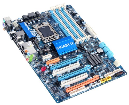
There are two more PCI Express slots located above the graphics slots that offer x1 and x4 support as well as two PCI slots that are positioned between the graphics slots and which are likely to be blocked by the graphics cards.
In addition there are six memory slots that support up to 24GB of triple channel DDR3-2100 memory, eight SATA ports (six on the ICH10R Southbridge and two on an add-in controller), one Firewire, and eight USB 2.0 ports on the I/O panel. Curiously enough there are no brackets in the package to take advantage of the USB and Firewire headers but most high-end cases include a selection of ports so that shouldn’t be a problem.
The layout of the board is slightly unconventional as the floppy and IDE connectors are located at the foot of the board while the power and reset micro buttons are positioned outboard of the memory slots next to the main power connector. This is a neat arrangement if you plan on using a SATA DVD drive as the SATA connectors are laid down and feed the cables away from the board with the minimum of fuss.
The heat pipe system snakes across the motherboard and connects aluminium coolers on the Southbridge, Northbridge and six phases of the 12-phase power system. The other six phases have a separate cooler, as though another couple of inches of heatpipe would have broken the bank. Perhaps it all depends on the bank in question. Change up to the UD5 or Extreme models and you get a more substantial cooling system but we are confident you will be happy with the system that is employed on the UD4P. During our testing we didn’t use any case fans and the temperature of the chipset cooler was stable at 45 degrees C.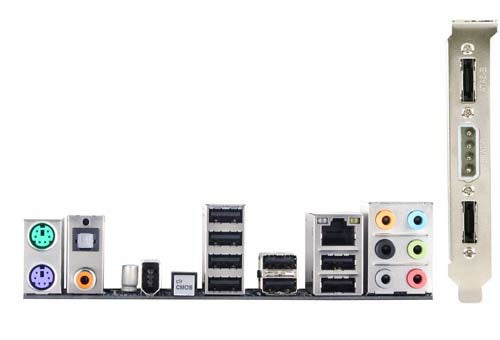
Gigabyte puts an emphasis on the construction of its latest motherboards both in respect of the Ultra Durable 3 components and also the doubling of the amount of copper that is used in the board. We like Ultra Durable 3 and feel that it makes Gigabyte motherboards very similar to high-end models from Asus however we also feel that the DrMOS components used on MSI motherboards such as the X58 Platinum are even better.
The doubling of the amount of copper in boards such as the UD4P sounds impressive and the motherboard is certainly very stiff but it is impossible to judge whether that is thanks to the use of a 70 micron layer of copper instead of the usual 35 microns. Similarly we can tell that that the UD4P is very cool in operation but that has been true of every Core i7 motherboard that we have seen to date.
The array of ports on the I/O panel is comprehensive but despite that there seems to be quite a lot of unused space. There are two PS/2 ports next to the digital audio connections, then the single Firewire sits in glorious isolation and next to that we have the illuminated Clear CMOS button. Four USB ports are in a stack next to the switch followed by four more USB and the Gigabit Ethernet with six analogue mini jacks to finish. We’d be happier if the Clear CMOS button had more room around it and would have liked to see at least one eSATA port but broadly speaking we were happy with the layout of the UD4P and also with the list of features.
We hit a minor snag when we tried to get the Gigabyte running as we initially used memory slots one, three and five instead of two, four and six. As a result the system appeared to be dead until we did some detective work. The manual put us straight however we would have hoped for some sort of POST debug display as the UD4P is covered with LEDs. These show details such as the power phases when they are in operation which makes them essentially cosmetic. We fixed the memory problem in a matter of moments but even so we would trade all of the flashing lights for a spot of timely help.
Our initial efforts with the UD4P were uninspiring and we found it tricky to overclock our Core i7 965 Extreme beyond 3.7GHz until Gigabyte rode to the rescue with its overclocking guide for the EX58 Extreme. This guide also applies to the other X58 models in Gigabyte’s product range and made it clear that we had missed a trick. You need to disable Intel Turbo Boost when you overclock Core i7 and this feature is tucked away in the depths of the BIOS. Once that was sorted our processor zipped along at 3.9GHz without a hitch. 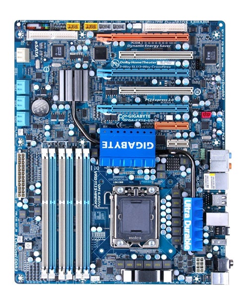
We were able to raise the memory speed from 1,066MHz on a base clock speed of 133MHz to 1,200MHz on a base clock of 150MHz. With Turbo Boost running we had been forced to reduce the memory speed to 900MHz to avoid blue screens.
Raising voltages in the BIOS is a simple task that is helped by a system of colour coding. Safe voltage figures appear in yellow with higher settings in purple. If you try to save a purple setting the BIOS gives a warning that ‘the following settings will reduce the life of the components’. Take it a step further and the voltage settings turn red and the warning changes to tell you that the ‘critical voltage setting may damage the component’.
One of the voltage settings that is employed by the Gigabyte overclocking guide took us into purple territory and we’re none too sure that we would have clicked ‘OK’ to the warning that the life of the motherboard would be reduced if we didn’t have the official say-so from Gigabyte.
Once you’ve set the voltages and adjusted the base clock speed and clock multiplier you can also employ Gigabyte’s dynamic Performance Enhance overclocking settings. The options consist of Disabled, Standard and Extreme however it didn’t seem to us that these settings made a great deal of difference to performance.
It took a couple of days to investigate all of these settings and the upshot is that we were impressed by the quality of the UD4P and consider it to be very fair value for money.
”’Verdict”’
Gigabyte has put a great deal of effort into the BIOS of the EX58-UD4P and the result is a stable Core i7 motherboard that offers a very long list of options.
Trusted Score
Score in detail
-
Value 8
-
Performance 8
Editorial independence
Editorial independence means being able to give an unbiased verdict about a product or company, with the avoidance of conflicts of interest. To ensure this is possible, every member of the editorial staff follows a clear code of conduct.
Professional conduct
We also expect our journalists to follow clear ethical standards in their work. Our staff members must strive for honesty and accuracy in everything they do. We follow the IPSO Editors’ code of practice to underpin these standards.